SOLISCADA V7.70.00.01 is now available. Important Notice: License Key reactivation is required after updating. Learn what's new and update now→
 SOLISCADA at a Glance
 Architecture
 Why Choose Us
 Essential Functionalities
 Beyond the Basics
 System Recommendations
 FAQs
FAQs Oil & Gas
 Water Industry
 Food & Pharmaceuticals
 Marine
 Mining & Metal
 Manufacturing
 Electric Utilities
 Municipal Industry
Modbus communication fundamentally depends on the relationship between register (address) types and function codes. Together they determine how a Master accesses data inside a Slave device. Understanding how these two pieces fit is essential for reliable Modbus/SCADA integration.
1. Modbus register types & address ranges
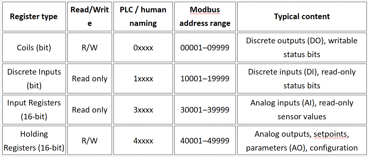
Modbus defines four primary data areas (register types). Each area has a conventional 4- or 5-digit logical address representation used for configuration and documentation. Actual communication uses zero-based offset addresses (i.e., the logical address minus the base for that type).
Key points:
a. Prefix digits (0, 1, 3, 4) are functional identifiers to help humans distinguish register types. These prefixes are not transmitted on the wire. The Modbus frame uses a zero-based offset inside the type region.
b. Logical address ranges (conventional notation) make configuration easier; when building a request frame you convert the logical address into an offset (starting at 0).
Common register types:
Address conversion example
Logical address 40001 (first Holding Register) → offset 0 in the request frame.
Logical address 40100 → offset = 40100 − 40001 = 99 (decimal) = 0x0063 (hex).
Logical address 40200 → offset = 40200 − 40001 = 199 (decimal) = 0x00C7 (hex).
Coil logical address 00005 → offset = 00005 − 00001 = 4 (decimal) = 0x0004 (hex).
Range limits
Theoretically addresses are 0–65535 (16-bit), but actual supported ranges depend on device memory mapping and implementation. Always consult the device documentation.
2. Modbus Function Codes
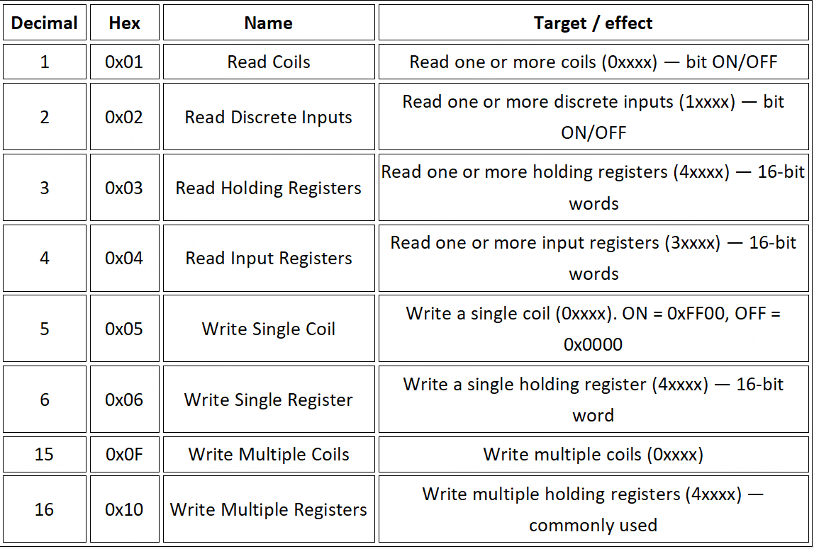
A Modbus function code is one byte in the request frame that tells the Slave what operation to perform (read or write) and which type of data to operate on.
Core (commonly used) function codes
Exception responses
If the Slave encounters an error processing the request (illegal function, illegal data address, illegal data value, etc.), it returns an exception response. The exception function code = original function code + 0x80.
Example: Master sends Function 03 (0x03) to read holding registers but requests an illegal address. Slave will respond with function code 0x83 (0x03 + 0x80) and include an exception code in the data field explaining the specific error.
3. How register addresses map to function codes
Function codes determine which register type you can access:
To read Coils (0xxxx) → use Function 01 (Read Coils).
To read Discrete Inputs (1xxxx) → use Function 02 (Read Discrete Inputs).
To read Input Registers (3xxxx) → use Function 04 (Read Input Registers).
To read Holding Registers (4xxxx) → use Function 03 (Read Holding Registers).
To write Holding Registers (4xxxx):
Single register → Function 06
Multiple registers → Function 16
To write Coils (0xxxx):
Single coil → Function 05
Multiple coils → Function 15
Important principles
a. Type matching: The function code must match the register type you intend to access. For example, using Function 03 to read logical address 30001 (an Input Register) is incorrect. Use Function 04 for 3xxxx addresses.
b. Address validity: The offset in the request must be within the defined range for that register type on the device. Accessing an undefined address will cause an exception response.
c. Read/write attributes: Respect read-only or write-only attributes. You cannot write to 1xxxx or 3xxxx (these are read-only).
d. Address conversion: Tools and PLC configuration often show logical addresses (e.g., 40001). Convert these to the zero-based offset when filling the Modbus request frame: offset = logical_address − base (e.g., 40001 → offset 0).
4. Application examples
Scenario 1: Read drive current speed (mapped to Holding Register 40100)
Function code: 03 (Read Holding Registers)
Start offset: 40100 − 40001 = 99 (decimal) = 0x0063 (hex)
Number of registers: 1 (assume speed occupies one register)
Example RTU request frame (hex / conceptual): [SlaveID] [03] [00] [63] [00] [01] [CRC]
Scenario 2: Start a motor (mapped to Coil 00005 set ON)
Function code: 05 (Write Single Coil)
Coil offset: 00005 − 00001 = 4 (decimal) = 0x0004 (hex)
Write value: FF00 (ON)
Example RTU request frame (hex / conceptual): [SlaveID] [05] [00] [04] [FF] [00] [CRC]
Scenario 3: Set target temperature (mapped to Holding Register 40200, value = 250)
Function code: 06 (Write Single Register)
Register offset: 40200 − 40001 = 199 (decimal) = 0x00C7 (hex)
Write value: 00FA (hex for 250)
Example RTU request frame (hex / conceptual): [SlaveID] [06] [00] [C7] [00] [FA] [CRC]
5. Summary & practical notes
a. Identify the data type first. Determine whether the point is discrete (bit) or analog/parameter (word), and whether it is read-only or writable. That determines whether you use the 0/1/3/4xxxx space.
b. Choose the correct function code. For read and write operations select the function code that matches the register type (03/04/06/16 are among the most commonly used).
c. Convert addresses for communication. Convert documentation/PLC logical addresses (e.g., 40001) into zero-based offsets when building Modbus frames.
d. Consult the device manual. The manufacturer’s documentation is authoritative: it specifies the exact register mapping, data formats (16-bit unsigned, signed, byte order, whether a value spans two registers as a 32-bit float or long, etc.) and which function codes the device supports.
e. Use tools to test and debug. Modbus master test utilities such as ModScan or ModbusPoll make it easy to send requests, inspect responses and debug mapping issues.
Mastering the mapping between register addresses and function codes is the foundation of successful Modbus communication. Always verify mappings and data formats against the specific device manual before writing control or configuration values.