SOLISCADA V7.70.00.01 is now available. Important Notice: License Key reactivation is required after updating. Learn what's new and update now→
 SOLISCADA at a Glance
 Architecture
 Why Choose Us
 Essential Functionalities
 Beyond the Basics
 System Recommendations
 FAQs
FAQs Oil & Gas
 Water Industry
 Food & Pharmaceuticals
 Marine
 Mining & Metal
 Manufacturing
 Electric Utilities
 Municipal Industry
In industrial automation systems, data sharing and integration are critical. SOLISCADA not only provides powerful data acquisition capabilities, but can also function as a standard Modbus TCP Slave server, publishing internal data for external access by host computers, MES systems, or other clients that support the Modbus TCP protocol. This article provides a detailed guide on how to configure and use this functionality.
1. Function Overview and Working Principle
The Modbus TCP Slave driver allows the SOLISCADA to function as a data server that listens on a specified network port. When an external Modbus TCP Master (such as another SCADA software, HMI, or data platform) sends a request, the SOLISCADA responds by mapping and providing the specified internal tag data—such as temperature, pressure, or equipment status—through Modbus registers, enabling one-way or two-way data sharing. The software supports data requests from up to 20 Modbus Masters simultaneously.
2. Core Configuration Steps
2.1 Adding and Configuring the Modbus TCP Slave Driver
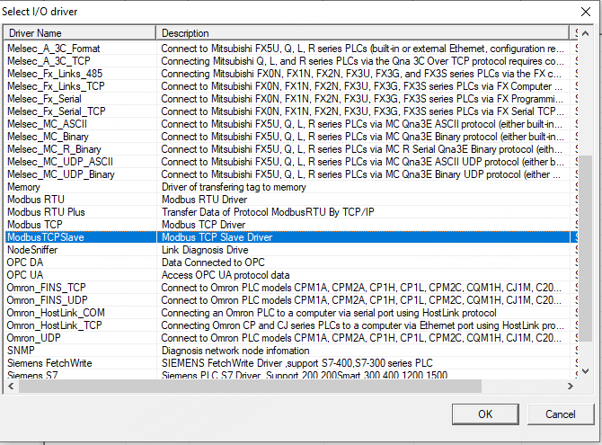
Add the Driver: In the SOLISCADA configuration software’s “I/O Driver Management” interface, click “Add Driver”. Then select the “Modbus TCP Slave” driver from the driver list.
Configure Data Block Properties: After adding the driver, create or select a Data Block under the Modbus TCP Slave Driver Configuration. Then configure the required parameters in the properties panel on the right.
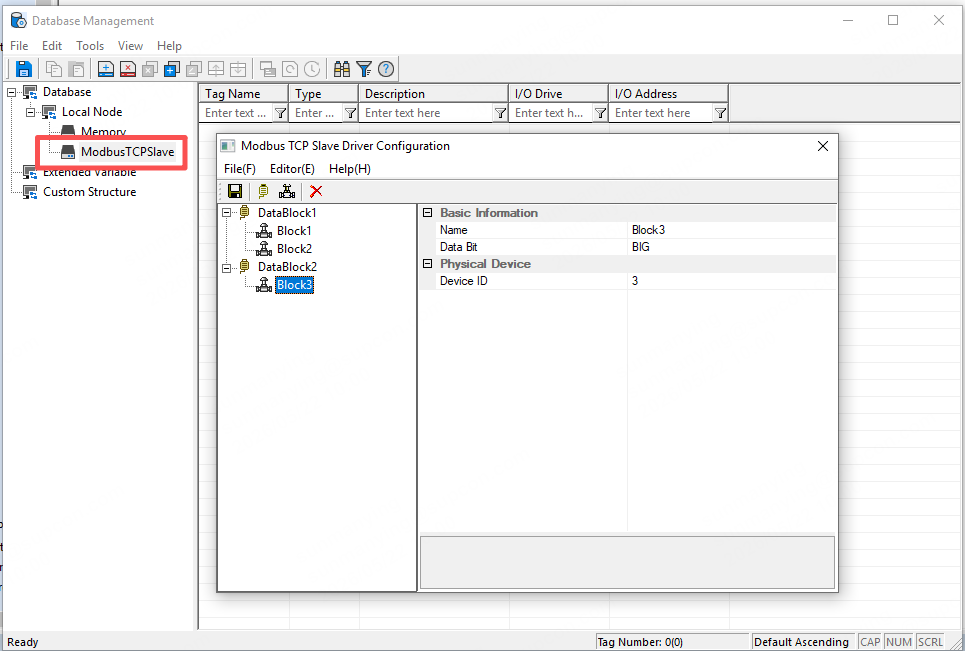
Local Port: Set the TCP listening port number. The default value is 502. Make sure this port is not blocked by the firewall and remains unique within the network.
2.2 Creating Devices and Data Blocks (Register Mapping Area)
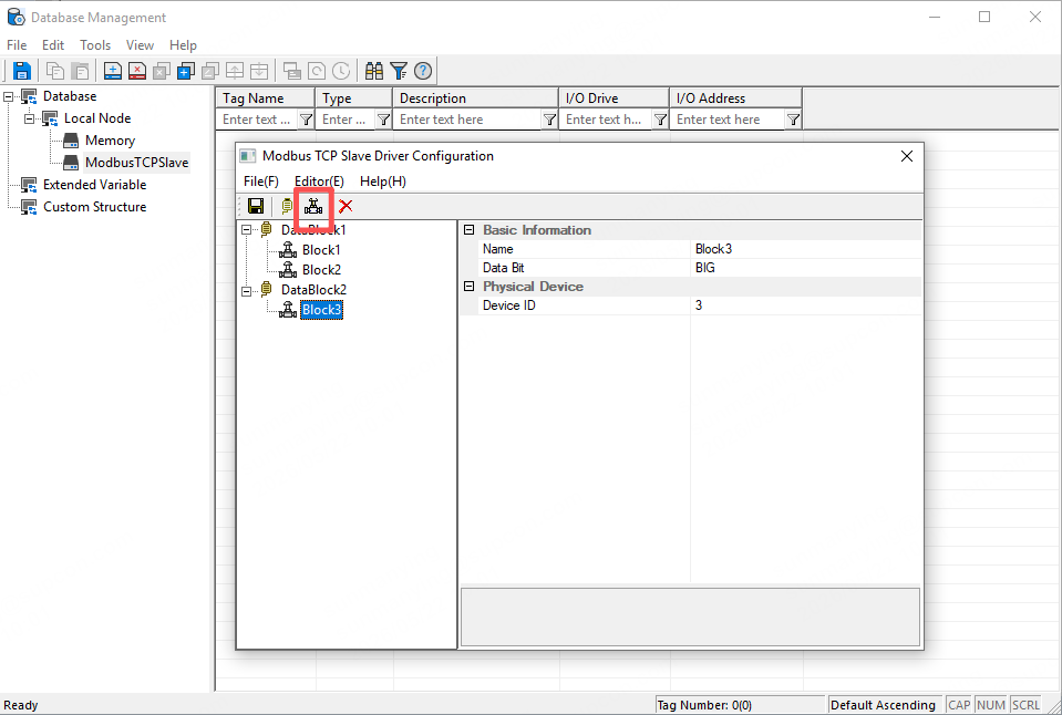
2.2.1 Adding a Device
Under the Modbus TCP Slave driver, add a Device node. This device represents a group of data that will be exposed to external systems.
Device ID: This is the Modbus slave address, with a default value of 1. External masters must specify this ID when establishing a connection.
2.2.2 Adding Tags
Add a tag under this driver. The I/O Address Configuration interface is shown in the figure below.
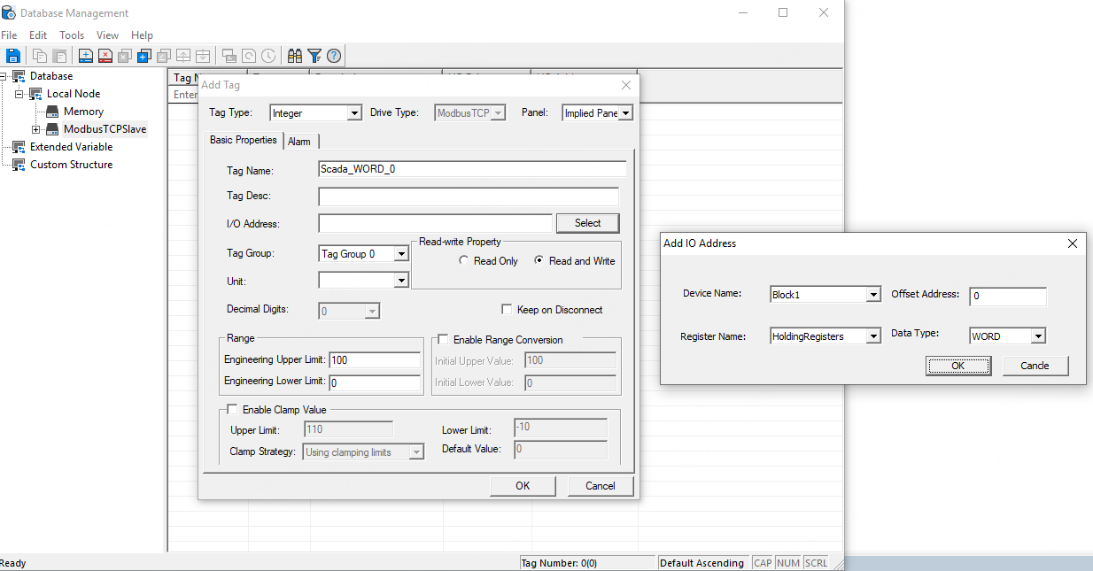
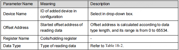
The Tag Name and Description can be configured according to actual requirements. The I/O address follows the format: Read/Write Data Block Name, Data Type Name, Offset Address.
Note:
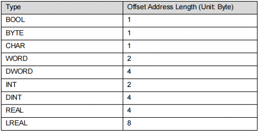
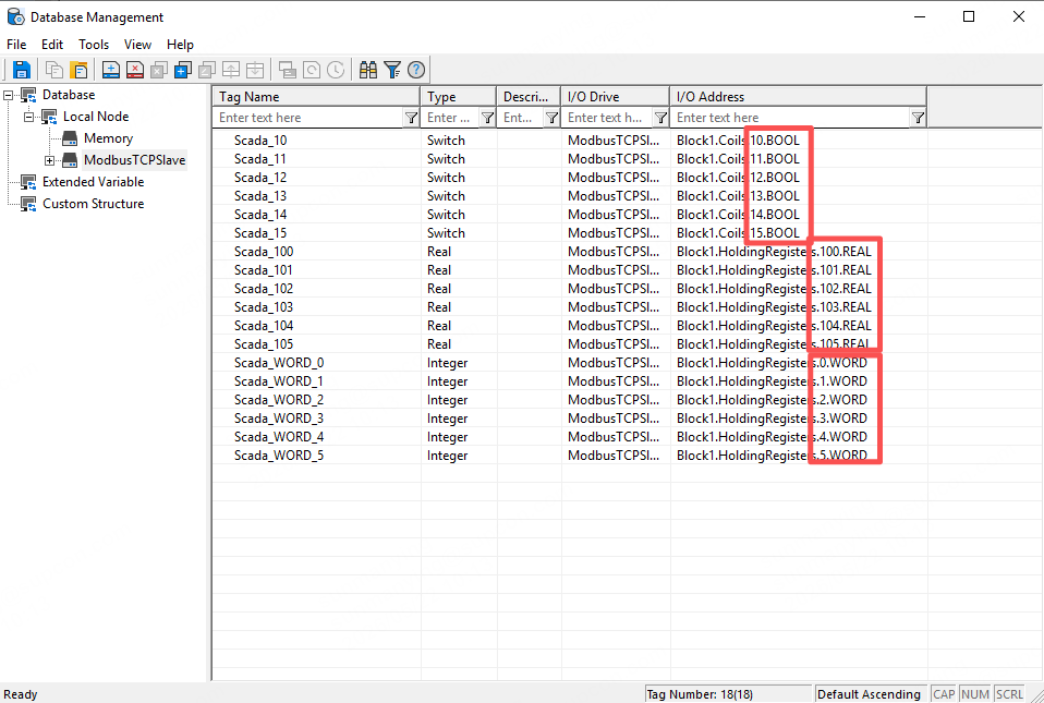
The Word data type occupies 2 bytes. When adding the next tag, the offset address should start from 1, and subsequent tags should increase by +1 accordingly.
The REAL data type occupies 4 bytes. When adding the next tag, the offset address should start from 2, and subsequent tags should increase by +2 accordingly.
2.3 Register Mapping
In Section 2.2, we added devices and tags. However, after the monitoring system starts running, the created tag values will default to 0 and only function as slave-side data points for external masters to read from or write to. If you need to forward data collected by other drivers, you must also map the real-time values of those tags.
In SOLISCADA, real-time value mapping can be implemented using VBS scripts or batch tag writing through scheduling tasks.
2.3.1 Scheduling Task – Batch Tag Writing
Create a Scheduling Task: In the configuration management software, navigate to the “Schedule” node of the target sub-project and create a new scheduling page.
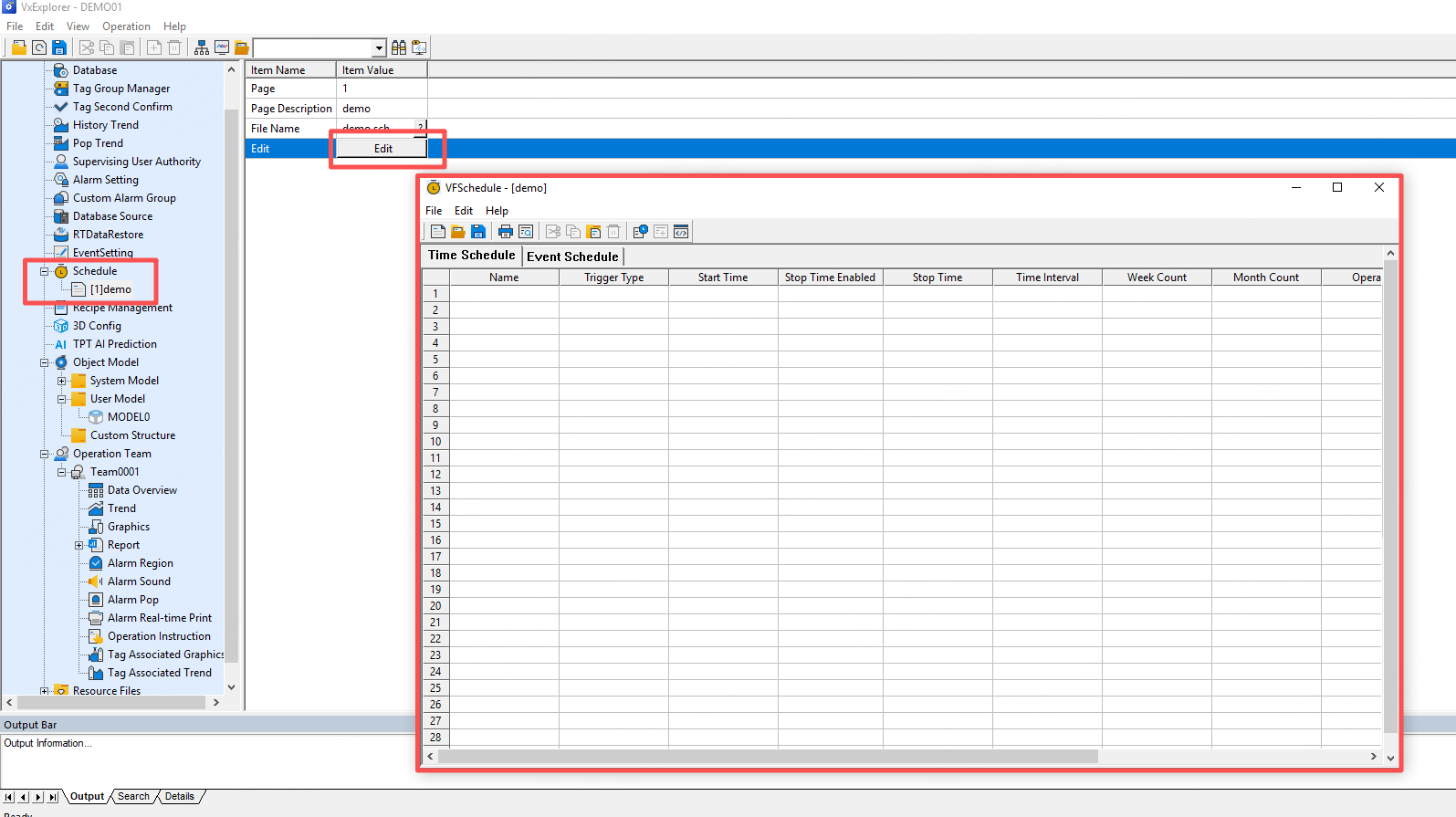
Add a Schedule: In the schedule configuration management window, navigate to the “Schedule” node of the target sub-project and create a new schedule page.
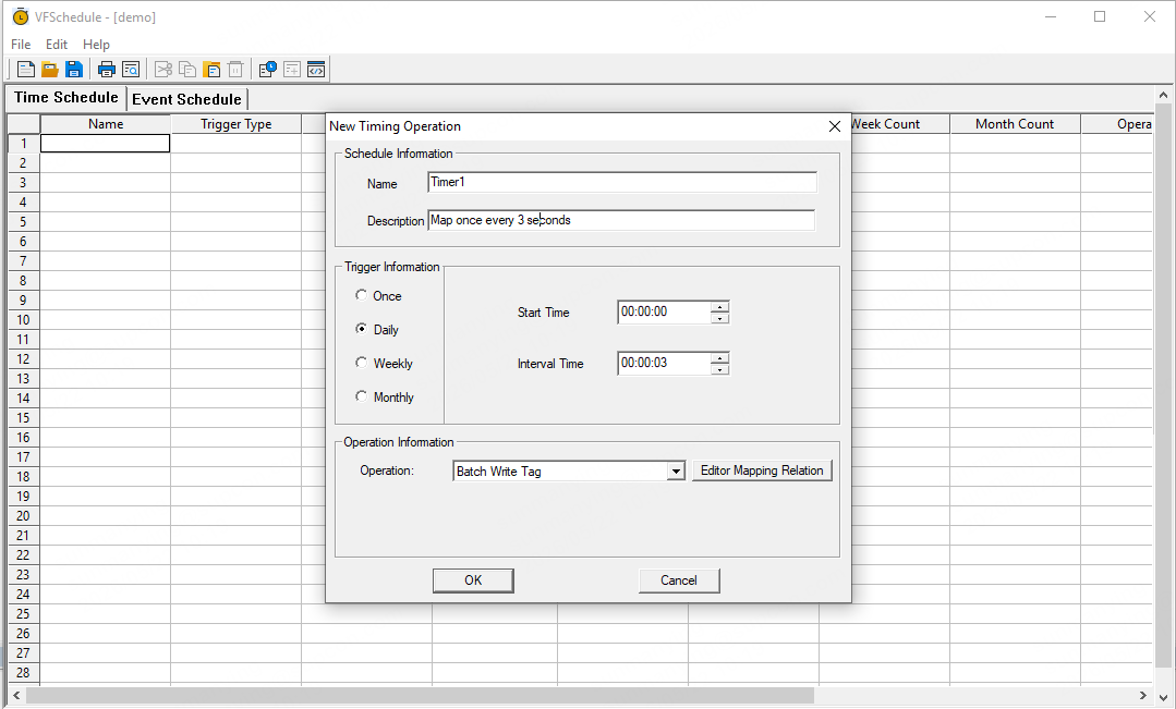
Select an Operation: In the “Operation Information” section, choose “Batch Write Tag” from the drop-down list.
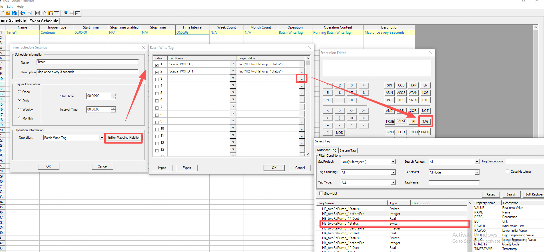
Edit Mapping Relation: Click the “Edit Mapping Relation” button to open the mapping configuration window.
Configure the Mapping Table: In the mapping table, specify both the “Tag Name” (the tag to be written to) and the corresponding “Target Value.”
Tag Name: Select the required tag using the tag selector.
Target Value: Specify the value or status to be written to the selected tag, such as a numeric value for analog variables or an ON/OFF status for digital variables. You can also reference the real-time value of a tag from another driver using Tag("Tag Name").
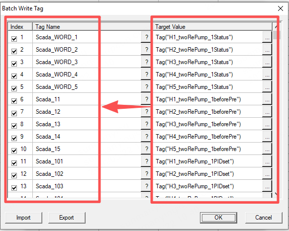
Confirm and Save: After completing the mapping configuration, click “OK” to save the settings. Once the scheduling task is triggered, the system will execute batch write operations for all specified tags according to the configured mapping table.
3. Third-Party Integration
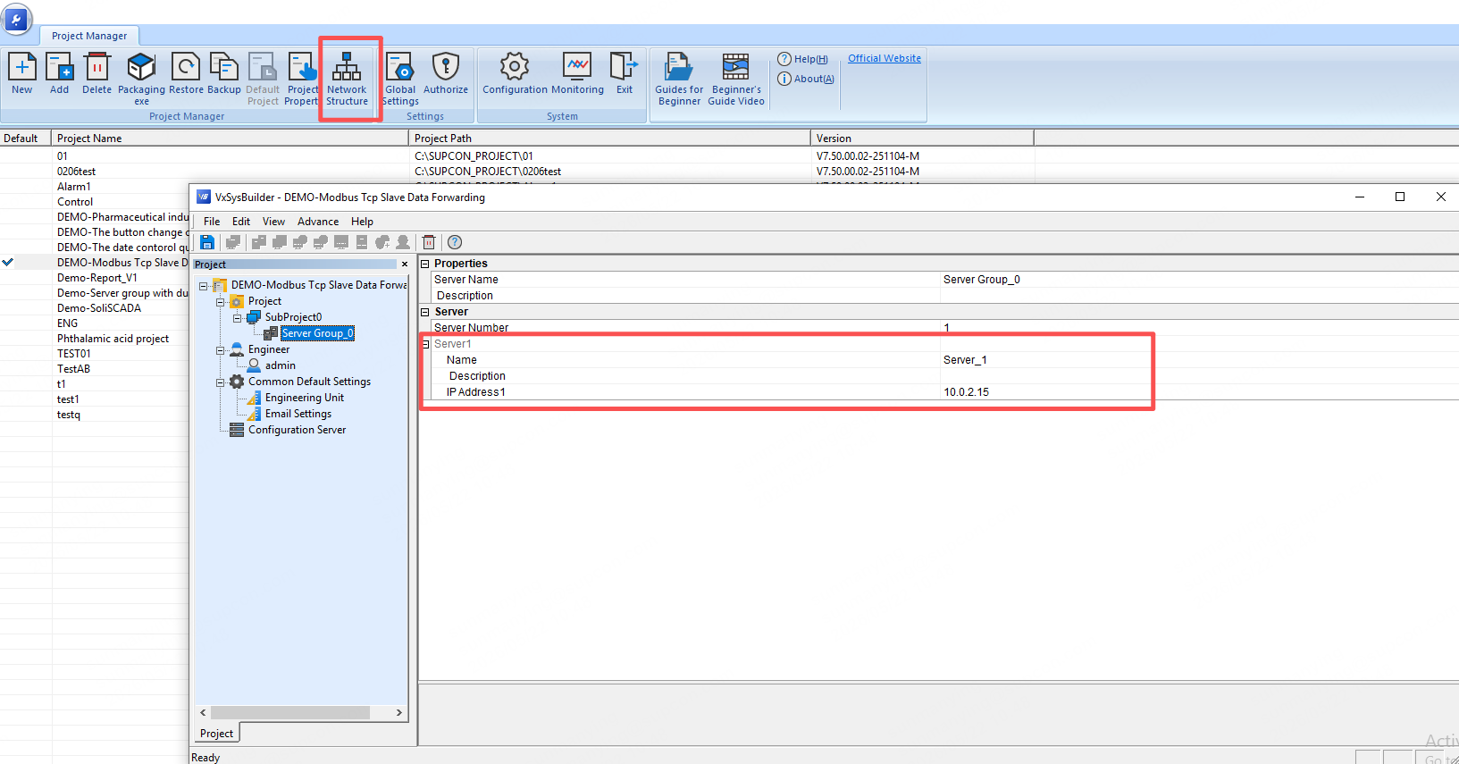
The default port number for the Modbus TCP Slave service in SOLISCADA is 502, and the IP address corresponds to the server group IP address.