SOLISCADA V7.70.00.01 is now available. Important Notice: License Key reactivation is required after updating. Learn what's new and update now→
 SOLISCADA at a Glance
 Architecture
 Why Choose Us
 Essential Functionalities
 Beyond the Basics
 System Recommendations
 FAQs
FAQs Oil & Gas
 Water Industry
 Food & Pharmaceuticals
 Marine
 Mining & Metal
 Manufacturing
 Electric Utilities
 Municipal Industry
The structure of a Modbus response (exception response) is very simple. When the master device (Master) sends a request, the slave device (Slave) will reply with a normal response if processing is successful; if an error occurs during processing, it will reply with an exception response.
Differences between an exception response and a normal response
1. Function code:
The function code in a normal response is the same as the requested function code (for example, if the request is 0x03, the normal reply is also 0x03). An exception response sets the highest bit of the requested function code (i.e., adds 0x80) to form the returned function code.
l Example: If the master requests to read holding registers (function code 0x03) and the slave reports an error, the returned function code will be 0x03 + 0x80 = 0x83.
2. Data field:
The data field of a normal response contains the requested data (such as register values). The data field of an exception response contains only a single byte, and this byte is the exception code, which indicates the specific error.
So, a complete exception response frame looks like this:
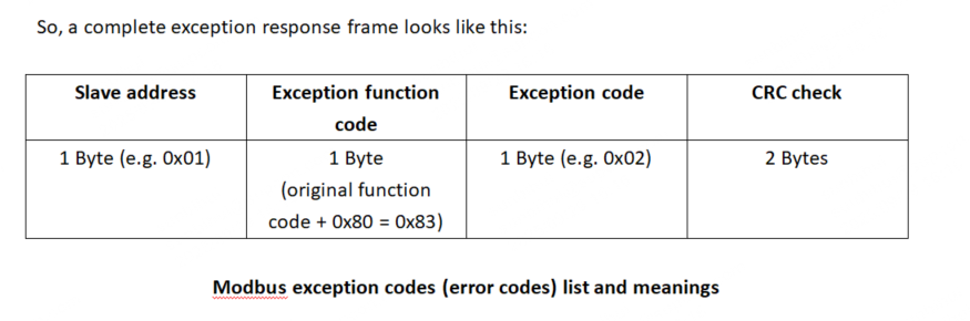 list and meanings.png)
The table below lists the standard Modbus exception codes, their meanings, and possible causes.
| Exception code (hex) | Exception code (dec) | Exception Name | Meaning / Explanation | Common Causes |
| 0x01 | 1 | Illegal Function | The slave has not implemented the requested function code. | 1. The master requested a function that the slave does not support (e.g., writing to a read-only coil). 2. The slave device model or firmware is older and has limited functionality. |
| 0x02 | 2 | Illegal Data Address | The data address specified in the request is not allowed by the slave. | 1. The requested register or coil address is outside the slave’s actual range (e.g., the slave has only 100 registers and the master requested address 120). 2. Address mapping errors — some addresses may be reserved or not enabled. |
0x03 | 3 | Illegal Data Value | The value contained in the data field of the request is illegal for the slave. | 1. A written register value is out of allowed range (e.g., writing 2000 to a register that only accepts 0–1000). 2. The number of registers requested is too many (the Modbus protocol specifies a maximum of 125 registers per read). 3. Incorrect data length |
0x04 | 4 | Slave Device Failure | An unrecoverable error occurred while the slave was processing the request. | 1. Hardware failure of the slave device. 2. Internal firmware/software error occurred while executing the requested operation. |
0x05 | 5 | Acknowledge | The slave has accepted the request and is processing it, but the processing requires a long time. The master should poll again later. | 1. The master requested an operation that takes a long time to complete (e.g., device reboot). 2. The slave requires the master to poll to confirm completion. |
0x06 | 6 | Slave Device Busy | The slave is busy processing a previous command and cannot handle the current request. | 1. Slave processing capacity is insufficient; command queue is full. 2. The master is sending requests too frequently. |
0x07 | 7 | Negative Acknowledge | The slave refuses to perform the programming function (commonly used for programming commands). | 1. Similar to 0x05, but indicates the slave rejects execution of the command. |
0x08 | 8 | Memory Parity Error | The slave detected a parity error in extended memory. | 1. Memory hardware fault in the slave device. 2. This code is relatively rare and usually relates to specific device hardware issues. |
| 0x0A | 10 | Gateway Path Unavailable | Typically related to a gateway device, indicating the gateway cannot allocate a path for the request. | 1. Gateway misconfiguration or gateway device fault. |
| 0x0B | 11 | Gateway Target Device Failed to Respond | The gateway failed to obtain a response from the target device behind it. | 1. The target device behind the gateway is offline, powered off, or has communication interrupted. 2. Incorrect address for the target device. |
How to troubleshoot these errors?
In SOLISCADA Database-Modbus related driver area, you can right-click the driver configuration and select a device’s data blocks to perform online debugging and view the messages.

When you receive an exception response, you can troubleshoot it using the following steps:
1. Confirm the error: First check the function code in the response. If the highest bit is set (for example 0x83) then this is an exception response. Then read the next byte to obtain the exception code (for example 0x02).
2. Interpret the code: Look up the exception code’s meaning in the table above. For example, 0x02 means Illegal Data Address.
3. Check the request:
- For 0x01: Verify the function code is correct and that the slave supports that operation.

- For 0x02: This is one of the most common errors. Check whether the request’s start address and quantity exceed the address range defined in the slave device’s manual. Note: Modbus addresses are usually zero-based, but some vendors’ documentation uses an ‘offset’ or ‘protocol address’ that is one-based and be sure to confirm which convention is being used.

- For 0x03: Check that the values being written are within the allowed range, or that the number of registers/coils being read/written does not exceed the limits (maximum 125 registers per request or 2000 coils).
- For 0x04, 0x08: Check the slave device status — these often indicate a hardware or firmware problem.
- For 0x05, 0x06: Reduce the request frequency, or implement a retry/backoff mechanism.

As shown below, the polling frequency is too high, the slave cannot return a normal response in time, causing the master to mistakenly treat the device as offline. Adjust the polling interval to 3000 ms or greater.

Normal packet send/receive (exchange) is shown in the figure below: